Fix a DC to AC Power Inverter
Fault Finding a Power Inverter
I decided to fix a SAMLUX (Model: PST-30S-12A) 300 watt 12 volt DC to 120 volt AC power inverter which failed outside of the warranty.
I first inspected for any blown fuse on the faulty power inverter, as predicted the 40 amp blade fuse on the circuit board was like new.
I disassembled the case and removed the heatsink clamps and slid out the main circuit board.
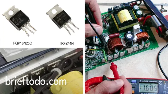
Now on to the main suspects the MOSFETs which come in a variety of packages, this board has two banks of four TO220 packaged MOSFETs and they should look something like the ones in the image below.
Some of the things I used.
- Soldering Iron Kit – https://amzn.to/3KjZWJq
- Heatsink Paste – https://amzn.to/3YX4BF2
- Silicone Thermal Pad – https://amzn.to/3Ehiea2
Identify and Test the MOSFET Transistors
Write down the MOSFET identities and search for them online to confirm they are definitely MOSFETs.
The three pin outs on these MOSFETs are the gate, drain and source the middle drain pin connects to the heatsink on top.
I wanted to test the MOSFETs without removing them from the circuit board to do this you will need a multimeter with a diode testing mode.
Place the positive probe on the gate pin which is the first pin on the left looking from the front or in my case the third pin on the right looking from the rear place the negative probe on top of the heatsink which connects to the drain pin.
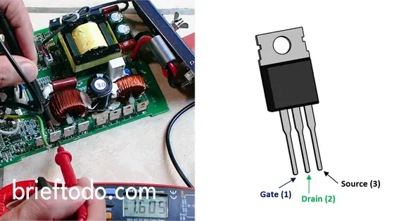
You should get a reading of 1 to 2 volts, the first two MOSFETs I tested give virtually no reading so they are dead and the next two look fine around 1.5 volts.
I turned the circuit board around and tested the second set of MOSFETs and they all gave a good reading. MOSFET banks should really be replaced altogether, I went ahead and removed the two bad ones and the two good ones.
I used copper solder wick to remove the majority of the solder, I then wiggled out the MOSFET pins with some thin nose pliers while still heating the solder pads.
You should use a decent soldering iron with 60+ watts or a soldering station when removing MOSFETs, it is possible to do this with a cheap 35 watt iron but you will have your work cut out.
Finding and Soldering the New MOSFET Transistors
I called around some local electronic component stores but no one had the original MOSFETs type FQP16N25C, but one shop did have some equivalent ones type SSP20N60C3 with slightly better specifications. The four MOSFETs to fix the power inverter came to just under $10 USD (2020)
I soldered the new MOSFETs to both sides of the double sided circuit board as they were originally installed.
Reassembly, Thermal Paste and Pads plus Testing
I then reassembled everything, also make sure to put some new thermal paste between the thermal pad and the MOSFETs and on the opposite side between the thermal pad and the main heatsink.
I tested the power inverter with a 120 AC volt device and it works fine, also the status light remains green and no longer goes to the abnormal amber light mode.
 brieftodo.com
 brieftodo.com